Power Utilization Effectiveness as a Capacity Planning Input
PUE sets your IT power budget before you place a single rack.
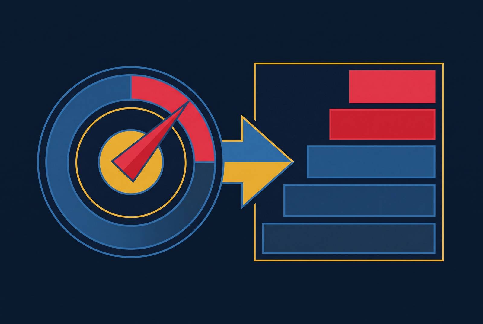
Power Usage Effectiveness tells you how much of a facility's total power is actually left over for IT equipment after everything else takes its share. That makes it a budget line, not a grade. Johnson Controls frames PUE in 2026 as the ratio between power going to IT and power going to the whole data center, and every watt spent on cooling, lighting, or distribution is a watt that never reaches a server. That simple division is what puts PUE ahead of every other capacity decision a team makes: it shapes layout, it sizes the cooling plant, it sets the limits of the power distribution system, and it does all this before a single rack gets placed on the floor. Utility power connections are getting harder to expand, and AI workloads are pulling more power per rack than ever, so the budget PUE describes is no longer soft. The extra capacity that used to hide inside oversized infrastructure is gone.
Some planners push back on using PUE as a fixed number, and they have a point: PUE shifts with climate, with how hard the IT load is running, with the season. But that variability is an argument for bounding the number, not for throwing it out. A conservative PUE target, modeled as a range instead of a single value, still constrains the IT power budget in a useful way. No constraint at all leaves the budget undefined, and an undefined budget is worse than an approximate one.
Why the industry average PUE has barely moved
The industry-wide PUE average has held roughly flat for years, and that stillness hides a split that matters more than the average itself. Older facilities are stuck running cooling plants and distribution systems that were never built for today's loads, and they can't fix that without a capital program, a new chiller plant, new switchgear, a redesign of the data hall. Newer builds, meanwhile, can reach PUE figures far below what the legacy fleet manages. Whichever side of that split a facility sits on, the capacity planner inherits it, since the flat average reflects the installed base carrying old inefficiency forward at the same rate new efficiency gets added.
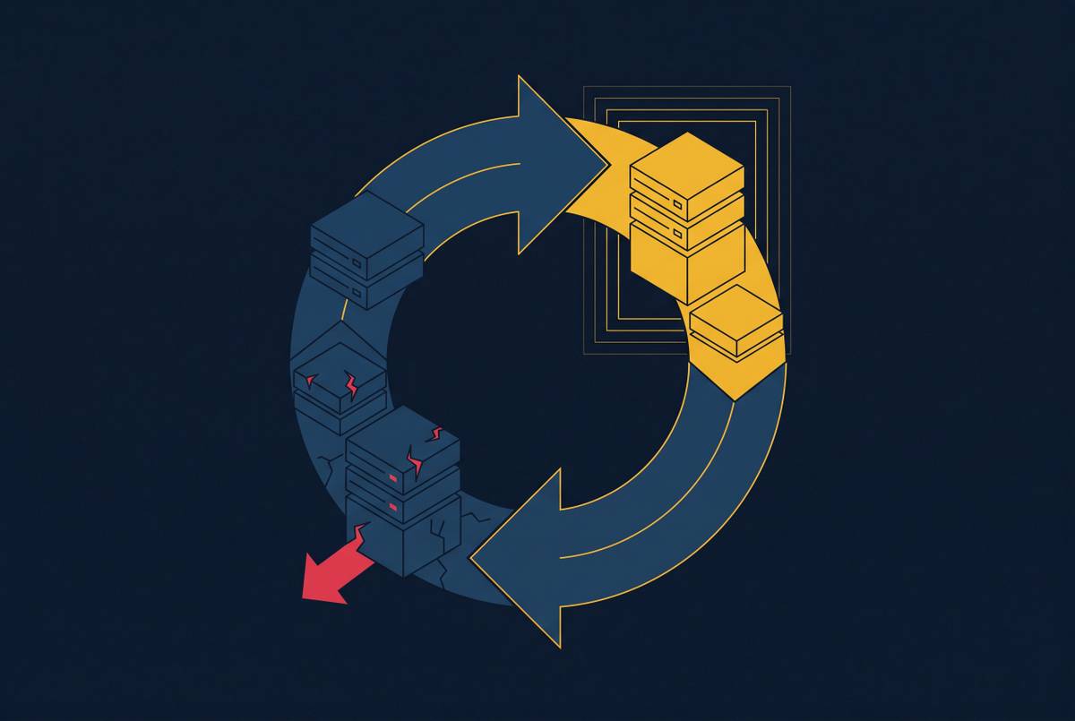
Part of the reason has to do with how AI workloads actually behave. Johnson Controls points out that training runs produce long, sustained heat loads, while inference work swings sharply between busy and idle. A cooling system that can't adjust to that swing ends up wasting power when the load is light and straining the grid when the load spikes, and both of those failure modes drag PUE down. The lesson for a design team building today is blunt: if the facility is sized against an industry-average PUE assumption, it's already been planned to waste a meaningful share of its incoming power on overhead. That waste isn't something that creeps in during operation. It gets written into the plan on day one.
PUE Limits, Rack Density, and Data Hall Layout
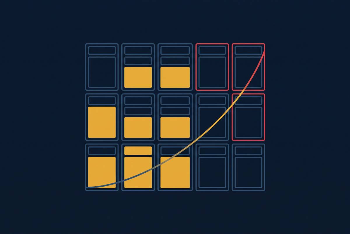
A PUE target, once set against a fixed utility connection, puts a hard ceiling on total IT power, and that ceiling decides how many racks fit, how dense they can run, and how the data hall gets laid out. Picture a facility with a fixed power draw from the utility and a PUE of 1.5. A third of that incoming power is gone before a single rack turns on. Bring the target down to 1.2 instead, and a meaningful slice of that lost third comes back as usable IT power, enough in many cases to add more high-density racks without asking the utility for a bigger connection.
That overhead fraction matters more today than it used to, not less, because AI rack densities have climbed sharply compared to general-purpose compute racks from five years ago. Many new facilities are now built around rack loads several times higher than what was standard a few years back, so every percentage point lost to overhead now costs more usable compute than it once did.
A layout built around a PUE of 1.5 looks physically different from one built around 1.2. The cooling plant takes up a different footprint, pipe runs follow different paths, floor loading changes, row spacing changes. PUE can't be bolted on after the layout drawing is finished. It has to shape the drawing from the start. Skip that step, and some sites end up unable to fully power racks that were designed to be fully populated, because the cooling and distribution systems around them already spent the power budget those racks needed.
Some layout tools let designers cap power at the rack level and treat that as good enough, on the assumption that PUE gets handled implicitly, but it doesn't. A rack-level cap says nothing about the overhead load sitting on top of it at the facility level, and without that facility-level PUE constraint, the sum of every rack's power budget routinely adds up to more power than the site can actually deliver.
Cooling system choice as the primary lever on the overhead fraction
Cooling takes up the largest share of non-IT power in a data center, which makes the choice of cooling architecture the single decision with the biggest effect on how much IT power budget is left over. Johnson Controls states it directly: improving PUE comes down to the efficiency of the systems rejecting heat back to the outside air, because cooling eats most of the non-IT power draw. A better cooling system lowers PUE, cuts operating cost, and frees up electrical capacity that can go straight to AI compute instead.
Cooling systems that can't track load variability cause real damage here. They overcool when the IT load is light, wasting power for no benefit, and they strain the grid when load spikes, both of which quietly erode the PUE the capacity plan was built around. That creates a dependency that a lot of planning processes miss: the PUE number used in the capacity plan only holds up if the cooling system delivers the efficiency it was specified for, across the full range of load the data hall will actually see, not just at one design point. A fixed assumption about cooling performance, checked only at one operating condition, produces an IT power budget that can't be trusted. Cooling selection and capacity planning are the same calculation, done by two different teams who need to be working from the same numbers.
What Breaks When PUE Is a Post-Build Measurement
PUE calculated after the fact, from metered totals once the facility is running, tells you nothing about whether the power budget it implies was ever enforced during design. By the time that number gets computed, the layout is fixed, the rack assignments are fixed, the cooling plant and power distribution are fixed, and the actual PUE might differ materially from whatever the capacity plan assumed going in.
This appears physically on the construction site, in the conflicts field teams encounter. Power systems, cooling equipment, cable trays, fire protection, and structural elements all compete for the same limited space, and when the drawings don't reflect the full overhead load correctly, field teams run into conflicts after installation has already started. Industry data puts this at 9.9 RFIs per $1 million of construction cost, on top of the redesigns, material substitutions, and schedule slips that follow. Treating PUE as something to measure later instead of something to design against now produces exactly these field conflicts.
The disconnection runs deeper than the construction site. Swapping in a higher-efficiency cooling plant partway through design should automatically recalculate the available IT power budget, the rack density the site can support, and the cable and power routing affected by the shift. In a fragmented workflow, none of that recalculation happens automatically. Someone has to do that recalculation by hand, or it doesn't get done. Each team ends up holding its own version of the truth: the cooling engineer works from one PUE assumption, the layout designer works from another, the capacity planner from a third, and nothing forces those three numbers back into agreement when one of them changes.
The same gap occurs again at the handoff between design and operations. On federal projects and other large builds where the schema connecting BIM, DCIM, and operational systems doesn't get defined until construction is already underway, integration teams run into a hard wall: the BIM was built to satisfy the architect's deliverable requirements, and the capacity data sitting inside it doesn't map to what DCIM actually needs to manage the IT power budget once the facility is live.
Connected systems engineering with PUE as a live constraint
A connected design workflow treats PUE as a parameter that stays alive through the whole process, not a number computed once the building is finished. Change any piece of the overhead load, the cooling plant, the power distribution system, the lighting design, and the available IT power budget recalculates automatically, surfacing any conflict with the rack assignments and layout commitments already on the table.
The mechanism is simple arithmetic, applied consistently. Total facility power and a target PUE get set as parameters up front. Every reduction in overhead load increases the IT power available. Every addition reduces it. Rack assignments and layout decisions downstream get checked against that live number, not against a static guess made at the start of the project and never revisited.
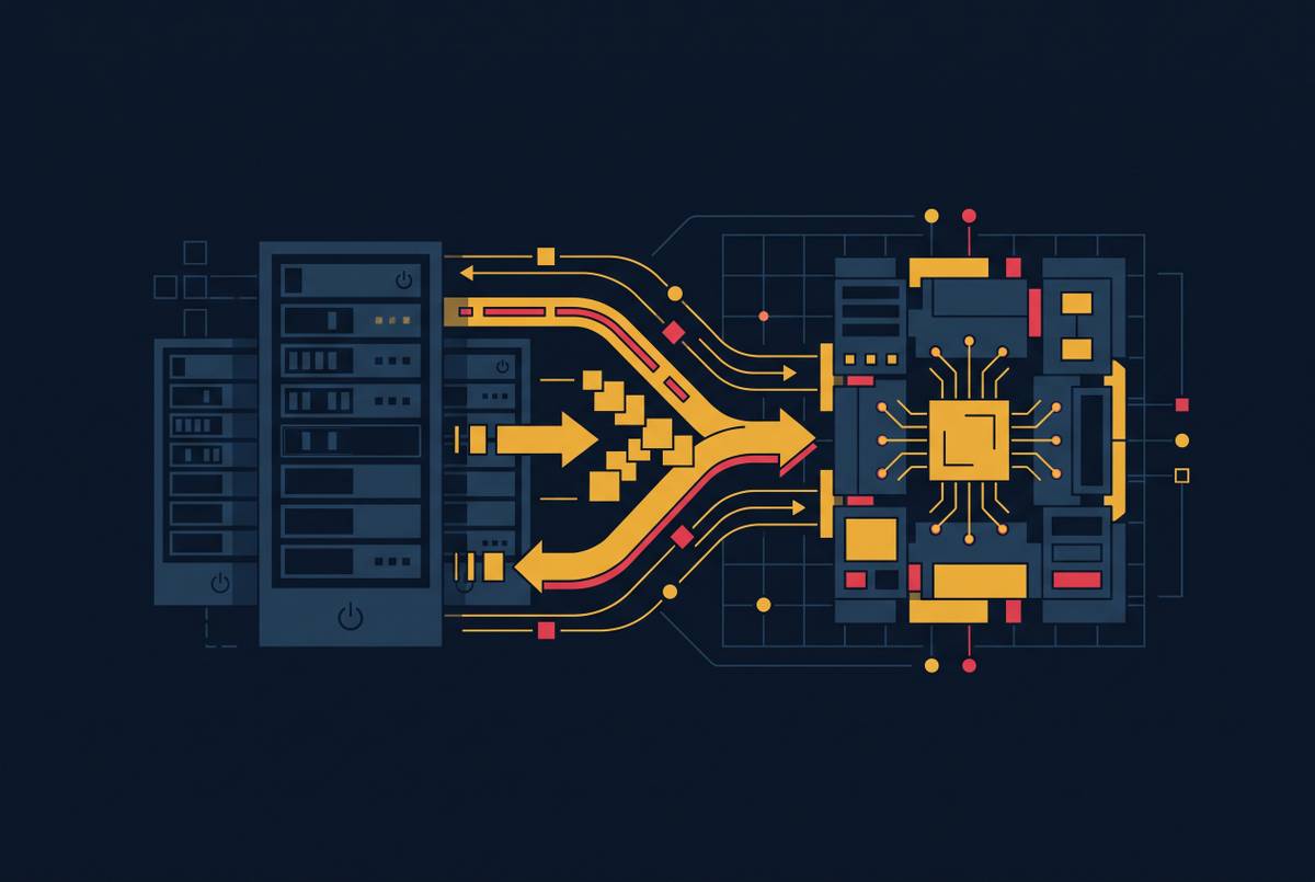
Moving a rack in this kind of model isn't just a physical relocation. It changes the local cooling load, the power draw on the distribution system, and the cable routing around it. A connected model propagates all three of those downstream effects automatically, instead of forcing someone to manually redo the power schedules, the cooling calculations, and the layout sheets by hand. This is the design-phase foundation that newer operational platforms depend on, the ones that pull data from EPMS, DCIM, and intelligent PDUs to enforce power caps at the rack and outlet level and prioritize which workloads keep running under constraint. None of that enforcement works if the design-phase model handed over the wrong IT power budgets at the rack and circuit level to begin with.
Modeling PUE as a live constraint also makes tradeoffs visible before they get built. A more efficient cooling system frees up IT power budget that can go toward additional high-density racks, and in a connected model, that tradeoff is something a team can see and weigh on screen, not something discovered after the concrete is poured.
Why PUE as a design input requires deterministic rules
Running PUE through a capacity model is a deterministic calculation. The overhead fraction is arithmetic, and the IT power budget that comes out of it has to be precise enough to govern real infrastructure commitments, racks, circuits, cooling plants. That precision rules out approximation.
AI has a real role in this process, but it belongs where ambiguity and judgment are the actual task: interpreting specifications that aren't fully spelled out, generating candidate layout options, flagging anomalies in operational data that a human should look at. The PUE-to-IT-budget calculation is a known ratio applied to a known total. An approximation that underestimates the overhead load by even a small margin produces rack assignments that draw more power than the site can actually deliver. Research on unified metric architecture for AI infrastructure cites Li et al. (2020) on exactly this point: PUE alone can't support fair comparison across sites because it's sensitive to climate, IT utilization, and design choices. That sensitivity means the inputs feeding the calculation need careful, traceable specification. They can't be guessed at by a generative model.
Deterministic rules that enforce PUE-derived power budgets at the rack and circuit level give critical-facility delivery something it needs: every rack assignment can be traced back to the overhead load calculation and the specific PUE target that authorized it. The same logic keeps code compliance checks rule-based. A wrong answer there doesn't just cost rework. It produces a physical installation that exceeds safe operating limits. AI and deterministic rules work as partners here, not substitutes: AI can propose a cooling configuration that improves PUE, and the rules engine checks whether the IT power budget that configuration produces actually satisfies every downstream rack and circuit commitment before anyone adopts it.
How PUE constraints must carry through to operations-ready handoff
An IT power budget enforced during design but never carried into operational systems leaves a facility with no way to check whether the overhead load it's actually running matches what the capacity plan assumed. DCIM is built mainly for monitoring and planning, not closed-loop control. BMS handles that closed-loop piece, running the cooling, environmental conditions, and safety interlocks in real time. Both systems need the same overhead load and IT power budget numbers the design model used, and both need those numbers expressed in a schema they can actually read.
That schema has to get defined early. When the handoff between BIM and DCIM isn't worked out until construction is already underway, integration teams run into the same wall described earlier: the BIM reflects the architect's deliverable requirements, not the structure DCIM needs, and the capacity data trapped inside the model doesn't map to operational records. Fixing that gap after commissioning costs far more than defining the schema up front, and it rarely gets fixed completely. The DCIM platform itself needs to be provisioned and partly configured before construction wraps up. Wait until occupancy, and the construction team has already demobilized, submittals are scattered across a dozen folders, and the window to capture accurate as-built data has closed. At that point, the IT power budget the capacity plan calculated can't be checked against what actually got installed.
Standards exist to close this gap. BS EN 50600-3-1 lays out which management system supplies which meter reading and what has to be available at handover. ISO/IEC 30134-2 defines how PUE itself gets measured and reported. Meeting both means the overhead load and PUE parameters built into the design model have to come out the other end in the data structures that operational systems are built to expect. Get that handoff right, and DCIM can do the job it's meant for: tracking whether the facility's actual overhead load still matches the PUE the capacity plan assumed, and flagging the moment operational drift starts eating into the IT power budget before any rack assignment asks the facility for more than it can deliver.